
In any automatic transmission-equipped race car, one of the most important elements separating the strong runners from all the rest is an efficient, properly matched torque converter. The evolution and development of the torque converter has made the automatic transmission a mainstay in drag racing for nearly 40 years, and now many entry-level circle track racers are discovering that automatic transmissions are much more consistent, reliable, and economical compared to manual transmissions.
A thorough understanding of torque converter components and terminology is necessary before setting out to make the proper converter selection. The torque converter is best described as a fluid coupling between the engine and transmission that performs the same function as a clutch in a manual transmission car; that is, it smoothly applies the engine’s power to the rest of the drive-line. The three major components of a torque converter are the pump, the turbine, and the stator.
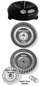
The pump – or driving member – of the converter consists of many curved steel blades, or vanes, that are housed in one half of the donut-shaped converter housing. The other half of the housing is occupied by the turbine – or driven member – of the converter which is also outfitted with curved steel vanes.
A simple comparison can be made between the pump and turbine assembly with two electric fans placed face to face. When one fan is plugged in and turned on, the blade begins to spin and pushes air toward the blades of the unplugged fan, causing them to spin, as well.
In a fluid coupler like the torque converter, transmission oil takes the place of the fan’s air currents. The pump drives the turbine as oil from the vanes on the pump side is forced into contact with the vanes on the turbine side.
There is one slight problem with this picture so far. As the fluid leaves the inner vanes of the turbine, it is thrown back toward the vanes of the pump in a direction which opposes the motion of the pump and can impede its movement. This is where the stator comes into play.
The stator also has curved vanes, but they are curved in such a way that they actually change the direction of the fluid coming out of the turbine, making it more helpful to the function of the converter at low speeds. The stator actually multiplies torque-as much as 2.6:1 when the pump is turning faster than the turbine.
In operation, the converter’s turbine will begin to catch up with the pump as the car comes up to speed. At this point, the stator is not needed. A one-way clutch, called a sprag, allows the stator to “freewheel” at higher speeds, preventing power loss from transmission fluid slowing the pump. In reality, the turbine will never completely catch up with the pump because the pump must always be turning faster than the turbine in order for the fluid to continue exerting force on the turbine vanes. The relationship ratio between pump and turbine is typically about 9:10…that is, the pump turns 10 times for every 9 that the turbine turns. This ratio is ideal for maximum torque multiplication and rapid acceleration.
In competition use, drag race converters will encounter more abuse than those used in circle track. For this reason, drag converters are more complex and more costly to manufacture. Heavy- duty sprags, needle thrust bearings, and super durable steel stators – much stronger than stock aluminum stators – all work to make a drag race torque converter stand up to high RPM launches time after time. Anti-ballooning plates (round steel plates installed on both the front and rear of the outside of the converter housing) prevent distortion and eventual destruction of the converter when it’s subjected to extreme load and heat.
Stall speed and flash stall speed (or flash point) are often misunderstood. Stall speed is the maximum engine RPM that can be attained with the brakes locked and gas pedal depressed, without the car moving. Flash stall speed is the point in the engine RPM range at which the car launches when the brake is released, and the accelerator is suddenly banged wide open. Flash stall speed is a more accurate method of judging a converter’s performance because a vehicle will often run quicker when accelerated from the starting line with the engine just above idle speed.
A properly selected converter should match the torque curve of the engine. A “loose” converter (very high stall speed) will suffer from excessive slippage and slow ET’s. A converter that is too “tight” (low stall speed) will have poor 60 ft. times and 1/4 mile ET’s, because the car is launching with the engine below its torque peak. As a rule, high-revving small block-powered cars will require a much “looser” converter than high-torque, big block-powered cars. A car with a 454 cubic inch engine will cause an identical converter to “flash” to a higher RPM than the same car with a 350 cubic inch engine, due to the additional torque of the big block.
Converters for circle track cars provide stall speeds comparable to OEM units, but they are engineered to eliminate lost horsepower through slippage. “Loose” enough to come out of the corners strong, yet “tight” enough to achieve a solid fluid “lock-up” on the straightaways.